Examples
Daedalus.Examples rebuilds the systems from six public engineering blog posts
by Modelon and Claytex, using components from the bundled library.
The vendor models and parameter sets behind those posts are not public. Each example therefore states:
- its source;
- what it reproduces;
- the parameter values that were assumed.
The aim is the same physics and the same kind of result plot, not identical
numbers. Every example has a regression test in
crates/daedalus-core/tests/library.rs, and CI simulates them all.
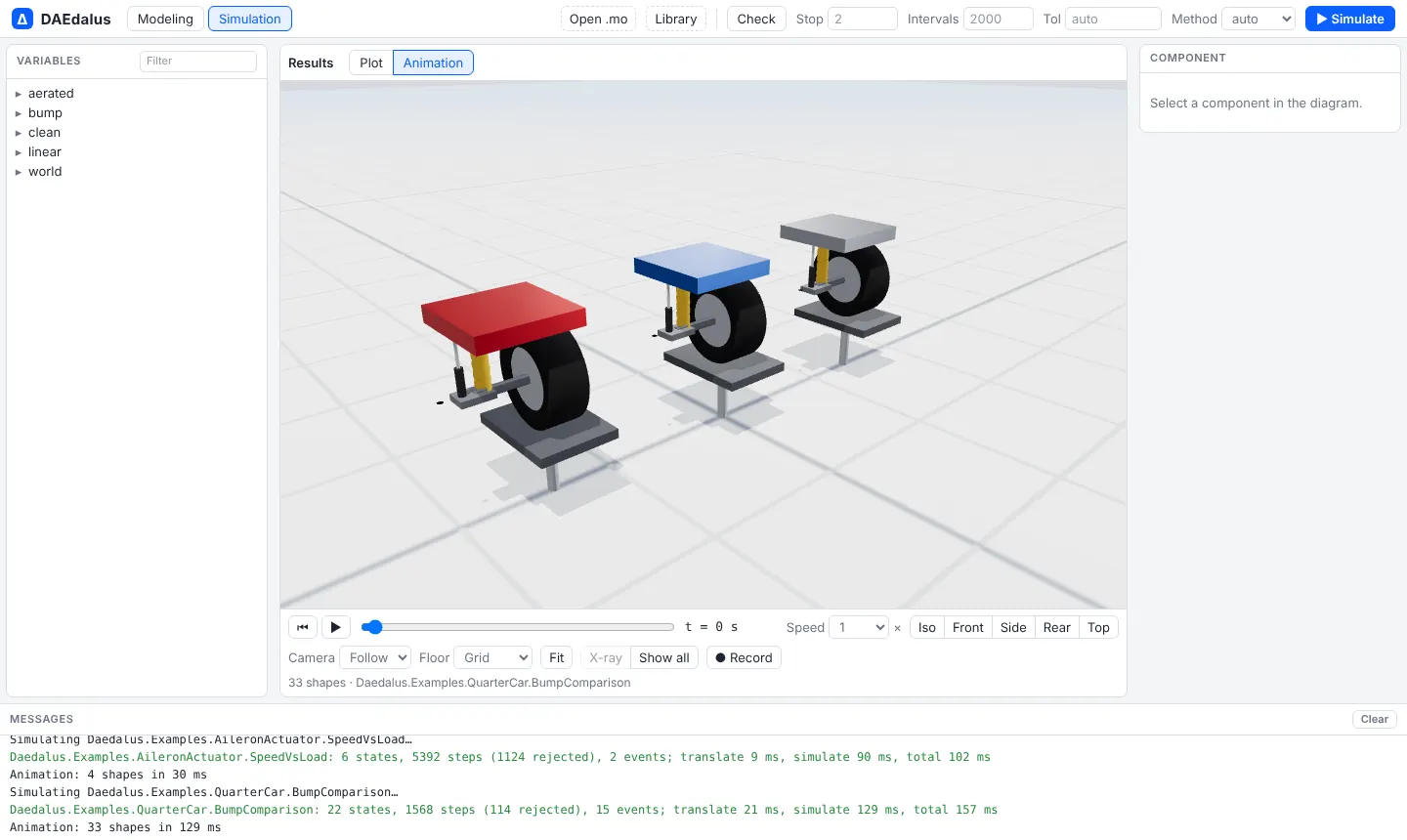
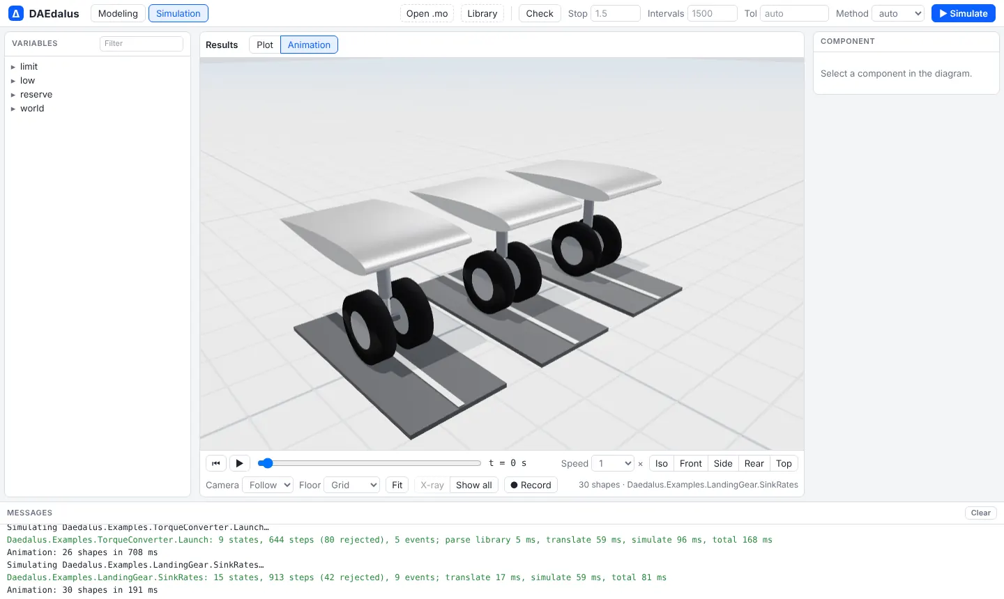
Every example also has a 3-D animation, as Dymola gives 1-D libraries: open it
in the workbench, Simulate, and switch to Animation. The shapes come
from Daedalus.Visualizers, which has the result variables of MultiBody's
Advanced.Shape without needing the Modelica Standard Library, bound to the
example's positions, angles and speeds. They draw only and change no result.
- QuarterCar and OptimalControl.ActiveSuspension: road pad, tyre, coil spring, damper and body for each lane, with the actuator force as an arrow.
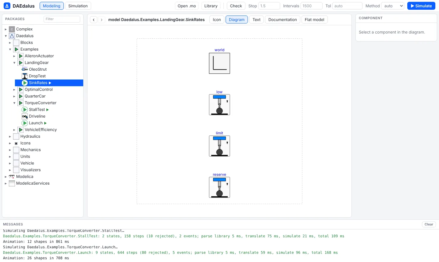
- LandingGear: a wing segment, the oleo strut stroking and the twin wheels on the runway, one lane per sink rate.
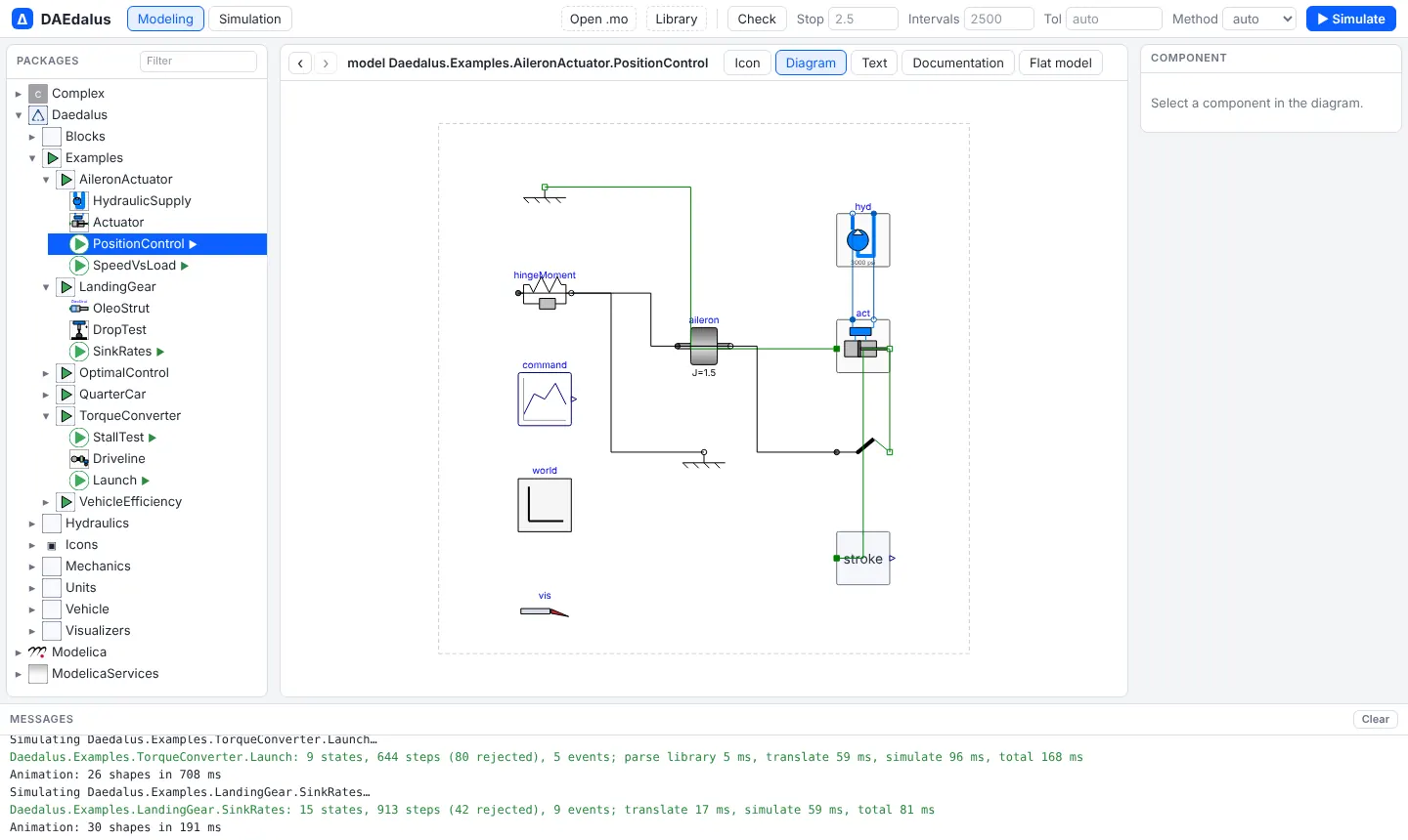
- AileronActuator and OptimalControl.AileronServo: the wing, the aileron turning on its hinge, the control horn and the actuator rod; SpeedVsLoad shows the load pushed along the bench.
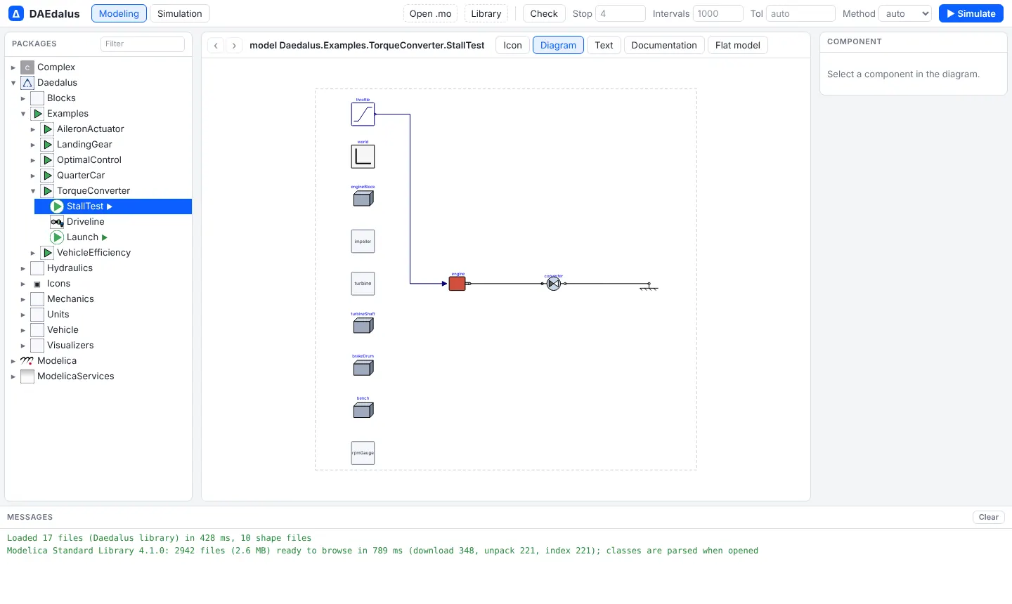
- TorqueConverter.StallTest: engine, the converter turning with the crankshaft, the held turbine and brake, and an engine-speed gauge.
- TorqueConverter.Launch and VehicleEfficiency: saloon cars (meshes in
Resources/Shapes, made bygenerate.pythere) driving side by side, one per variant, with the wheels turning. Long drive cycles replay at 10 to 100x.
Run any one of them with:
./target/release/daedalus simulate library/Daedalus -m Daedalus.Examples.<Package>.<Model> -o out.matOr open it in the workbench and press Simulate.
| Example | Source | States | Steps | CPU |
|---|---|---|---|---|
| TorqueConverter.StallTest | Claytex | 2 | 158 | 2 ms |
| TorqueConverter.Launch | Claytex | 9 | 644 | 13 ms |
| LandingGear.SinkRates | Modelon | 15 | 913 | 10 ms |
| AileronActuator.PositionControl | Modelon | 6 | 2,718 | 15 ms |
| AileronActuator.SpeedVsLoad | Modelon | 6 | 5,392 | 24 ms |
| QuarterCar.BumpComparison | Claytex | 22 | 1,563 | 28 ms |
| VehicleEfficiency.NEDCSensitivity | Claytex | 28 | 108,900 | 2.3 s |
| VehicleEfficiency.CoastDown | Modelon | 2 | 55 | 1 ms |
| VehicleEfficiency.UDDSEnergy | Modelon | 12 | 30,715 | 0.34 s |
Times are from daedalus test-library library/Daedalus -m Daedalus in a
release build, including translation.
Mechanical and automotive
Torque converter: stall test and launch
Source: Claytex, "Torque converters: the clutches of automatic transmissions" (claytex.com/tech-blog/torque-converters-the-clutches-of-automatic-transmissions/).
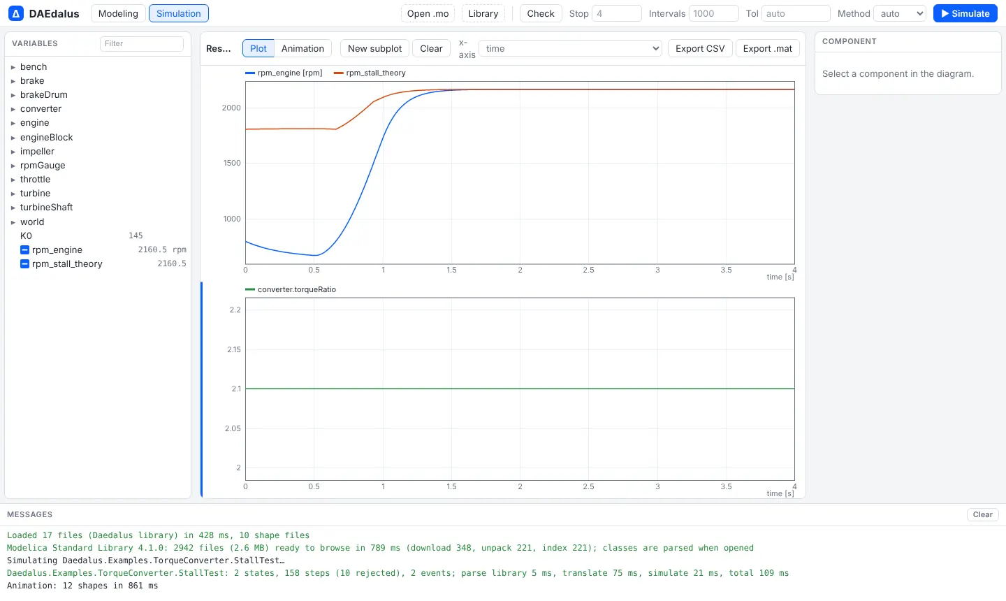
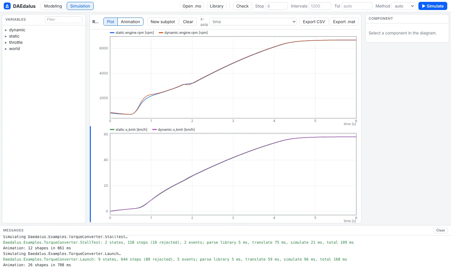
StallTest holds the turbine and runs the engine at full throttle. The engine
settles where its full-load torque equals the impeller torque (n/K)^2.
- Simulated stall speed: 2160 rpm.
- The K-factor prediction agrees to within 1 rpm.
- The turbine sees 2.1 times the engine torque.
Launch runs a full-throttle launch twice:
- once with a static K-factor converter;
- once with a 50 ms fluid torque build-up lag.
In both cases the engine flares toward stall speed and the torque ratio falls to 1 at the coupling point. The lock-up clutch then closes and pulls the engine down to turbine speed.
Assumed values:
- a generic three-element converter, K = 145 rpm/√(N·m);
- a 250 N·m engine;
- a 1700 kg car, first gear 4.2, final drive 3.2.
Open TorqueConverter.StallTest
Quarter car with a physical hydraulic damper
Source: Claytex, "A look inside VeSyMA's quarter car models" (claytex.com/tech-blog/a-look-inside-vesymas-quarter-car-models/).
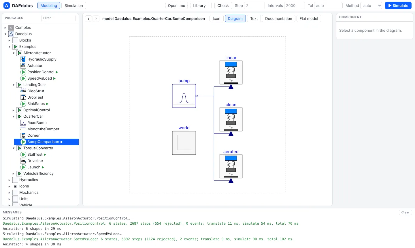
Three identical corners cross the same 50 mm bump at 10 m/s:
- one with an ideal linear damper;
- two with a monotube damper built from hydraulic components (rebound and compression valves, a bleed orifice and a gas-charged floating piston), once with clean oil and once with 2 % entrained air.
The tyre is an ElastoGap, so the wheel can leave the road.
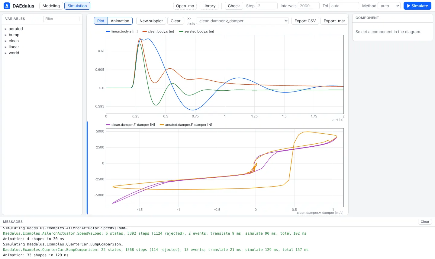
Results:
- The hydraulic damper's force-velocity curve is asymmetric and digressive
(
clean.damper.F_damperagainstclean.damper.v_damper). - Aerated oil adds series compliance, which shows as a hysteresis loop.
- All three bodies return to ride height (0.6 m) within 2 mm.
Assumed values:
- 400 kg quarter body and 40 kg wheel;
- 30 kN/m spring and 250 kN/m tyre;
- 46 mm piston and a 20 bar gas charge.
Open QuarterCar.BumpComparison
Vehicle efficiency sensitivity over NEDC
Source: Claytex, "Sensitivity testing of vehicle efficiency using VeSyMA drive cycle" (claytex.com/tech-blog/sensitivity-testing-of-vehicle-efficiency-using-vesyma-drive-cycle/).
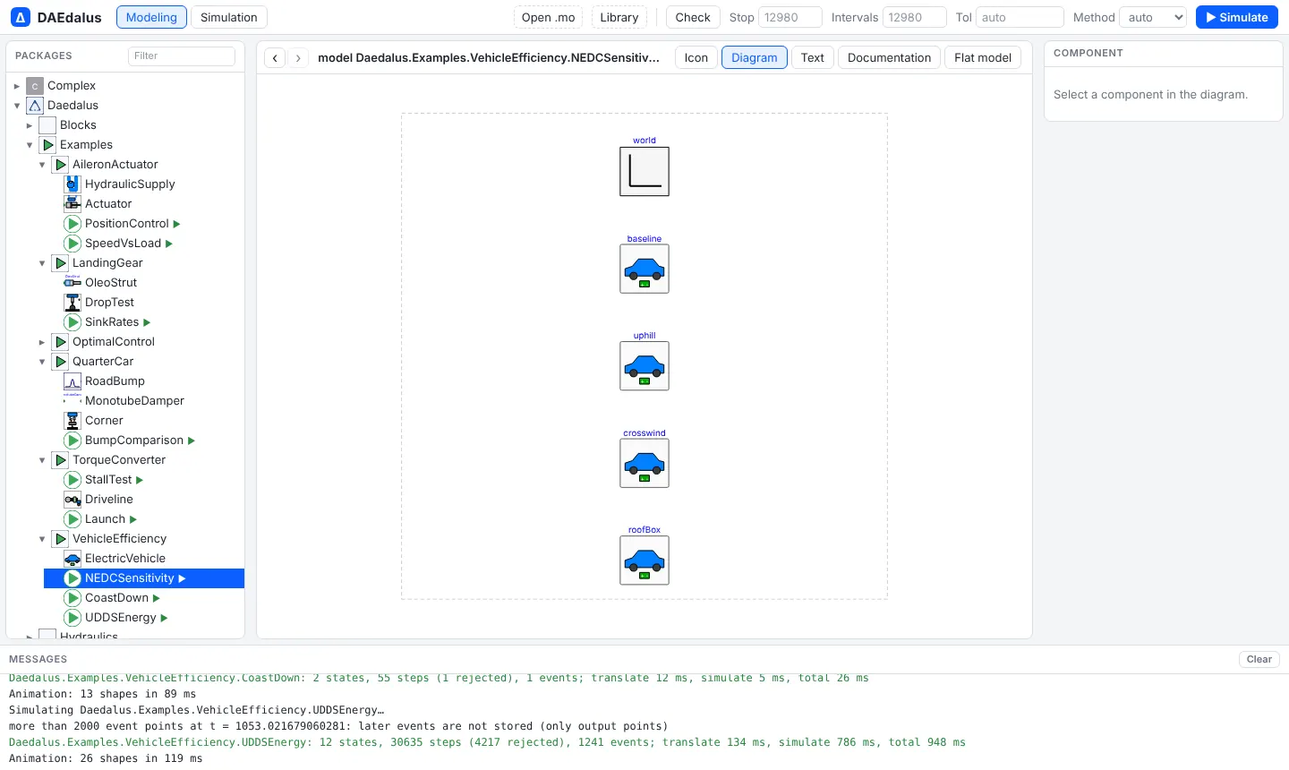
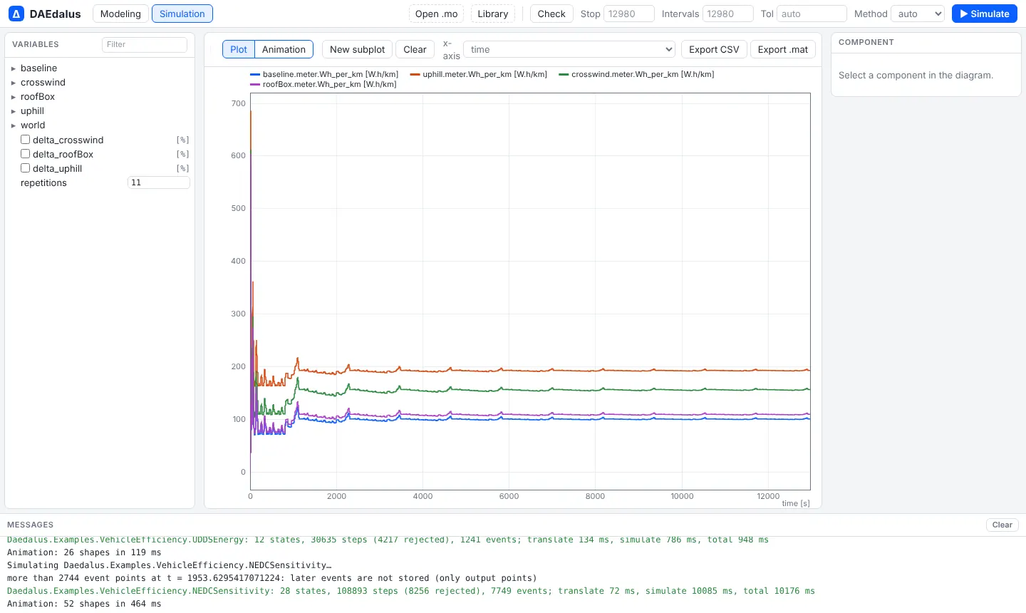
Four copies of an electric car drive 11 back-to-back NEDC cycles (12,980 s):
| Case | Wh/km | vs baseline |
|---|---|---|
| Baseline, flat road, still air | 100 | |
| 2 % grade | 192 | +92 % |
| 25 mph wind at 30° yaw | 156 | +56 % |
| Roof box (+50 kg, +0.12 m² drag area) | 109 | +8.9 % |
Crosswind raises drag through the yaw-dependent drag coefficient
Cd·(1 + k_yaw·β²).
Assumed values:
- 1650 kg car, Cd 0.29, frontal area 2.3 m², crr 0.009;
- 350 N·m / 150 kW machine with copper and iron losses;
- 9:1 reduction;
- 75 kWh pack.
Open VehicleEfficiency.NEDCSensitivity
Coast-down and road-load coefficients
Source: Modelon, "Advancing your vehicle's energy-efficient design" (modelon.com/blog/advancing-your-vehicles-energy-efficient-design/).
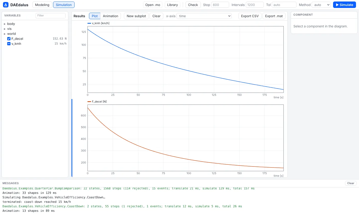
CoastDown lets the car roll from 130 km/h in neutral and terminates at
15 km/h. tools/fit_coastdown.py fits the recovered force to
F0 + F1·v + F2·v², giving F0 = 145.7 N, F1 = 0 and F2 = 0.4002 N/(m/s)².
That is exactly the physical rolling resistance and aerodynamic drag, as
expected.
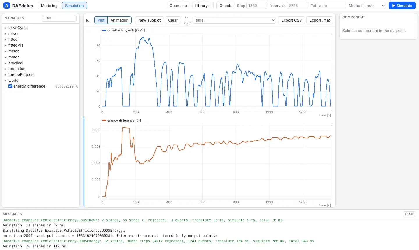
UDDSEnergy drives the EPA UDDS cycle twice:
- once with the physical body;
- once with a road-load vehicle that uses the fitted coefficients.
The two energy consumptions differ by 0.007 %. The UDDS schedule comes from NREL FASTSim.
Open VehicleEfficiency.CoastDown
Open VehicleEfficiency.UDDSEnergy
Hydraulic and aerospace
Landing-gear drop test
Source: Modelon, "Aircraft landing gear design" (modelon.com/blog/aircraft-landing-gear-design/).
This is a CS/FAR 25.723 style drop test. The sprung mass sits on an oleo-pneumatic strut, with a polytropic gas spring, a quadratic orifice, seal friction and end stops. The unsprung axle rides on a tyre, and wing lift equals the weight.
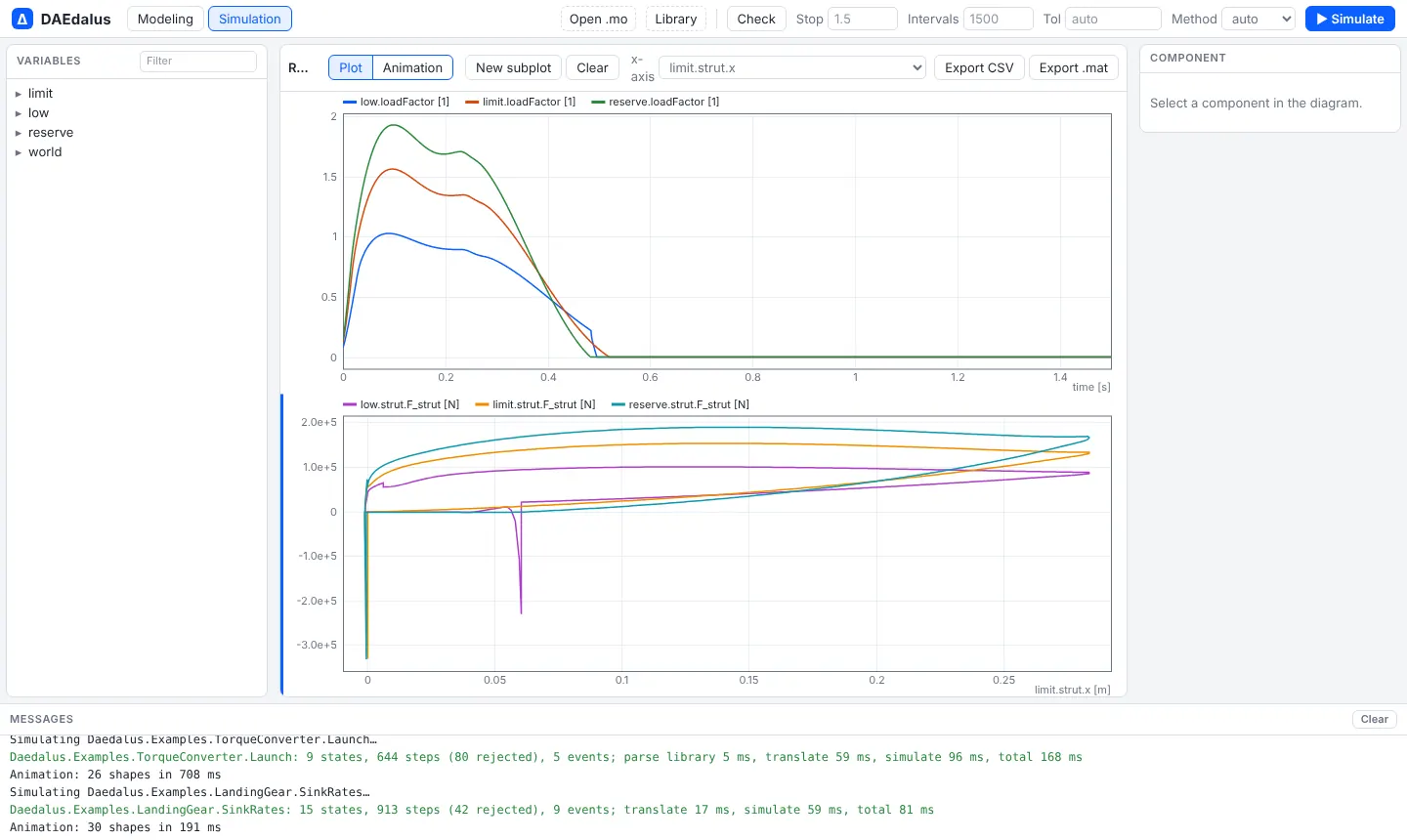
| Sink rate | Load factor |
|---|---|
| 2.0 m/s | 1.03 |
| 3.05 m/s (limit) | 1.56 |
| 3.66 m/s (reserve energy) | 1.93 |
The strut does not bottom out in the reserve-energy drop. The force-stroke loop
(limit.strut.F_strut against limit.strut.x) gives a shock-absorber
efficiency near 0.9.
Assumed values:
- 10 t per main gear;
- 150 mm piston and 0.4 m stroke;
- 30 bar precharge and a 5 cm² orifice;
- polytropic exponent 1.3;
- 2 MN/m tyre.
Aileron actuator
Source: Modelon, "Modeling and simulation of aircraft aileron actuator" (modelon.com/blog/modeling-and-simulation-of-aircraft-aileron-actuator/).
The system:
- a 3000 psi supply with a 50 psi return and 3 m lines;
- a flow-control servo valve with second-order spool dynamics;
- a balanced through-rod cylinder that moves the aileron through a control horn, against an aerodynamic hinge moment.
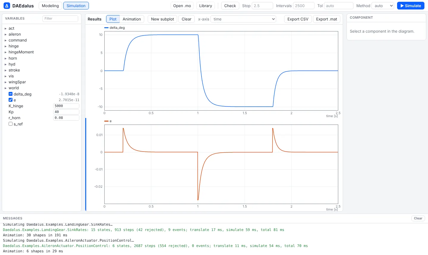
PositionControl steps the command to +10° and then to −10°, followed by a sine. The surface reaches each step within 0.2°.
SpeedVsLoad holds the valve fully open and ramps the opposing force to 95 % of stall force. The rod speed falls monotonically with load and stays below the ideal square-root valve law, because of line losses, friction and laminar flow at small openings. It is still moving at 95 % load.
Assumed values:
- 40 mm bore, 20 mm rods, 60 mm stroke;
- a 20 l/min valve at 70 bar with a 100 Hz spool;
- an 80 mm horn.
Open AileronActuator.PositionControl
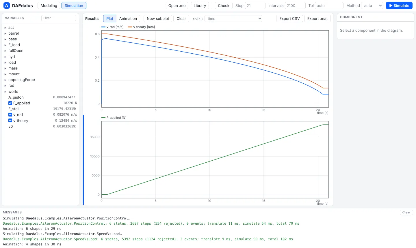
Open AileronActuator.SpeedVsLoad
Multibody suspension and full vehicle
library/MultiBodyVehicle has suspension corners, test rigs and a full car built on
Modelica.Mechanics.MultiBody, with nine examples checked against OpenModelica. They have
their own page: Multibody vehicles.
Optimal control plants
Daedalus.Examples.OptimalControl holds three plants whose control or unknown
inputs are top-level input variables or free parameters. They are solved with
CasADi from python/examples/; see optimal-control.md.
- AileronServo: the aileron actuator without its position loop. The
servo-valve command
uis the input. - ActiveSuspension: a quarter car with a force actuator
F_actand a soft passive damper, over the same 50 mm bump. - CoastDownTest: the coast-down without the stop at 15 km/h. It is used to
estimate
body.Cdandbody.crr.
Note on sources
From the build environment, modelon.com and claytex.com returned HTTP 403. The examples were therefore built from what the posts describe:
- the system;
- the test procedure;
- the quantities plotted.
They were not checked against the posts' exact figures.